Cadence System Design and Analysis

4.5K posts

Cadence System Design and Analysis banner
Cadence System Design and Analysis

Cadence System Design and Analysis

@CadenceSDA

OrCAD X - Your all-in-one PCB design tool for first pass success & quick-turn boards. Design faster, smarter, and with confidence. Start your free trial today!

Katılım Kasım 2009
256 Takip Edilen1.3K Takipçiler
Sabitlenmiş Tweet
Cadence System Design and Analysis
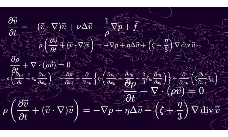
There is one area of mathematical physics and engineering that continues to challenge systems designers: fluid dynamics. Learn about the primary equations for compressible and incompressible flow in fluid dynamics in this article. bit.ly/339qI45 #cadence #CFD
Cadence System Design and Analysis tweet media
English
0
22
119
13.2K
Cadence System Design and Analysis
Your HDI impedance is calculated. Your stackup is correct. But if resin didn't fully flow during lamination, voids are already locked into the board — and your EDA tool will never show them. Glass Dk ~6-7. Resin Dk ~3. One diffpair trace over glass, the other over resin = measurable skew at multi-gigabit rates. Kirsch Mackey on resin flow physics, fiber weave effects, and the 11° routing fix 👇 ow.ly/6xzx50YBniz #PCBDesign #HDI #SignalIntegrity #AllegroX
Cadence System Design and Analysis tweet media
English
0
0
0
40
Cadence System Design and Analysis
Your HDI design passes DRC and BGA via clearances are legal but your planes are Swiss cheese and your power delivery is suffering because of it. Anti-pad accumulation under dense BGAs is a failure mode that is invisible to design rule checks. Watch this video to learn how to fix that. #PCBDesign #HDI
English
0
0
0
49
Cadence System Design and Analysis
Most HDI boards don't fail because of routing errors. On April 22, Kirsch Mackey walks through exactly these upstream decisions inside Allegro X, using a NVIDIA Jetson-based carrier board as the live design vehicle. 👉 Register here: ow.ly/kEGo50YHaw7 #PCBDesign #HDI
Cadence System Design and Analysis tweet media
English
0
0
0
33
Cadence System Design and Analysis
Solder mask layers have always displayed as negative in PCB design. You see the inverse of reality and have to mentally flip it to verify. That is where review errors happen. Release 25.1 fixes it with Positive Masks. What you see is what gets built. Read the full blog 👇 ow.ly/hAtv50YBrX9 #PCBDesign #AllegroX
Cadence System Design and Analysis tweet media
English
0
0
0
27
Cadence System Design and Analysis
Your PCB passed DRC. Your layout looks clean. Then the fab shop comes back with questions, and the clock stops. It happens because most designers hand off boards optimized for the EDA tool, not for the fabricator. Trace geometry that only tight-tolerance shops can handle. Thickness callouts that no multi-layer vendor can actually hold. Fabrication notes that are either missing or so exhaustive the CAM department needs a week just to digest them. By the time the questions land in your inbox, you've already invested in every component on that BOM. John Burkhert's latest blog gives you the field-tested framework to stop that from happening: ✅ Why reference designs will mislead you. Vendors build app notes with unlimited space and ideal isolation. Your real board won't have either. Part selection at the schematic stage defines your PCB technology before layout even begins. ✅ The geometry thresholds that keep your board quotable. Traces and spaces above 100 microns (4 mil) on outer layers and 76 microns on inner layers means almost any fab shop can build your board in under a week. ✅ The one tolerance you should never tighten. PCB thickness holds ±10% on a multi-layer board. Full stop. If mechanical or electrical engineers push back, the fab shop will prove you right. ✅ A complete 10-point fabrication notes template. From IPC-6012 Class 2 through electrical test per IPC-9252, with an explanation of what each note actually buys you. ✅ How to build an as-built file. Capture vendor show-stoppers after Rev. 1, keep a change log, and arrive at every future tape-out with a shorter list of technical questions. Read the full breakdown 👇 ow.ly/UJ4M50YzUCI #PCBDesign #DFM #OrCADX #Electronics
Cadence System Design and Analysis tweet media
English
0
0
0
46
Cadence System Design and Analysis
In HDI, a microvia only connects adjacent layer pairs. A signal crossing 3 layers needs 3 vias. At each one, the return current must also change reference planes — and if you haven't planned for that, it finds its own path. At DDR5 edge rates under 100ps, that's ringing. At PCIe Gen5/6, it closes the eye. Kirsch Mackey on stitching strategies, BGA return path traps, and what disciplined HDI stitching actually looks like. 👉 ow.ly/FFBf50YAQQX #PCBDesign #SignalIntegrity #HDI #AllegroX
Cadence System Design and Analysis tweet media
English
0
0
0
18
Cadence System Design and Analysis
Your HDI stackup looks right. Your vias look fine. Then fab calls. Join Kirsch Mackey on Apr 22 to walk through a full HDI workflow inside Allegro X. Real stackup decisions, BGA breakout routing, and DFM validation on a NVIDIA Jetson carrier board. Free. Live. Actionable. 👉 Register now: ow.ly/pyG050YBq8Q #PCBDesign #HDI #AllegroX
Cadence System Design and Analysis tweet media
English
0
0
0
81
Cadence System Design and Analysis
Teams rely on generic via templates. The HDI board 'looks' fine. Then it fails EMI. SI margins come in tighter than simulation predicted. Long-term reliability surprises follow. Dan Beeker's session on via and reference-plane transitions as electromagnetic systems. On Demand now. Watch the recording here: ow.ly/c0yH50YBVN1 #PCBDesign #HDI #AllegroX
Cadence System Design and Analysis tweet media
English
0
0
0
29
Cadence System Design and Analysis
0.35mm BGA pitch leaves you ~4 mils between pad edges. One 3-mil trace. No fan-out. Every signal through a via-in-pad. And that's before you deal with 500W of heat in a credit-card footprint warping your board mid-operation. Kirsch Mackey wrote the routing density and thermal strategy guide for this class of design. Read it: ow.ly/CRBN50YAMCI #PCBDesign #HDI #AIHardware #AllegroX
Cadence System Design and Analysis tweet media
English
0
0
0
32
Cadence System Design and Analysis
What happens when a switch is open in a power circuit? Does the electric field on the source side become purely static, similar to the field across a charged capacitor? Daniel Beeker answers questions from his 'Physics-Based Foundations for Power Supply Design' webinar. Didn't catch the webinar? You can find it here: ow.ly/lwVc50YvQfR #PCBDesign #DesignThinking #AllegroX
English
0
0
0
27
Cadence System Design and Analysis
PCB Designers! Have a PCB design you're proud of or one that posed tough challenges? Now’s your chance to gain valuable insights from Dan Beeker and Kirsch Mackey, two seasoned engineers with decades of experience in production-grade hardware. 💡 How It Works: 1️⃣ Submit a form with your background & design description. 2️⃣ Dan & Kirsch will review submissions and contact selected participants. 3️⃣ Featured designs will be reviewed in a technical video on Cadence channels! 👉 No design files needed to submit. Ready to learn from the best? Click below to get started! ow.ly/EopH50YBfFp #PCBDesign #DesignReview #AllegroX
Cadence System Design and Analysis tweet media
English
0
0
0
278
Cadence System Design and Analysis
Your component won't place. The schematic says pin 17. The footprint says G1. Nothing moves until someone fixes it. When nobody owns the library, that someone is always you. Mid-layout. John Burkhert on IPC-7351 tiers, thermal via footprints, and when to outsource the problem entirely: ow.ly/4ilo50YzU6M #PCBDesign #LibraryManagement
Cadence System Design and Analysis tweet media
English
0
0
0
26