Engineering Clarified

1.6K posts

Engineering Clarified banner
Engineering Clarified

Engineering Clarified

@EngClarified

Engineering Clarified

Katılım Mart 2024
6 Takip Edilen26.9K Takipçiler
Engineering Clarified
Engineering Clarified@EngClarified·
Strap footing with shearing force and bending moments for the strap beam
Engineering Clarified tweet media
English
0
3
27
913
Engineering Clarified
Engineering Clarified@EngClarified·
Find 1. Seepage flow 2. Pressure at A and B 3. Uplift pressure per unit length of dam
Engineering Clarified tweet media
English
1
8
61
2.2K
Engineering Clarified
Engineering Clarified@EngClarified·
Determine the angular accelerations of CB and AB at this instant??
Engineering Clarified tweet media
English
0
3
50
1.6K
Engineering Clarified
Engineering Clarified@EngClarified·
Bending Moment Diagram (k-ft) Qualitative Deflected Shape
Engineering Clarified tweet media
English
0
13
96
2.5K
Engineering Clarified
Engineering Clarified@EngClarified·
A 100 mm x 300 mm rectangular beam carries a uniformly distributed load of "w" kN/m over its entire span. The beam is freely supported at its ends. If the max. allowable bending stress is 8.27 MPa and simultaneously the max. allowable shearing stress is 0.70 MPa.
Engineering Clarified tweet media
English
2
14
84
2.9K
Engineering Clarified
Engineering Clarified@EngClarified·
Table 3-1: Approximate Values of Effective Length Factor, K The buckled shape of the column is shown by dashed line.
Engineering Clarified tweet media
English
2
10
85
2.3K
Engineering Clarified
Engineering Clarified@EngClarified·
A vertical, force P at A and another vertical force at B in the figure produce a resultant of 100 N down at D and a counterclockwise couple C of 200 N · m. Find the magnitude and direction of forces P and F.
Engineering Clarified tweet media
English
0
6
64
1.6K
Engineering Clarified
Engineering Clarified@EngClarified·
STRUCTURAL ANALYSIS 💛 Shear Force and Bending Moment diagram
Engineering Clarified tweet media
English
1
10
88
2.3K
Engineering Clarified
Engineering Clarified@EngClarified·
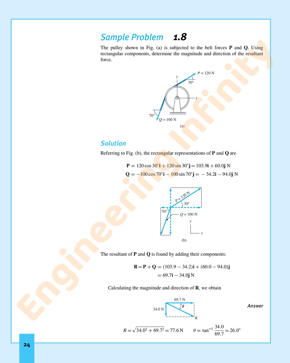
Sample Problem 1.8 The pulley shown in Fig. (a) is subjected to the belt forces P and Q. Using rectangular components, determine the magnitude and direction of the resultant force.
Engineering Clarified tweet media
English
0
1
15
1.1K
Engineering Clarified
Engineering Clarified@EngClarified·
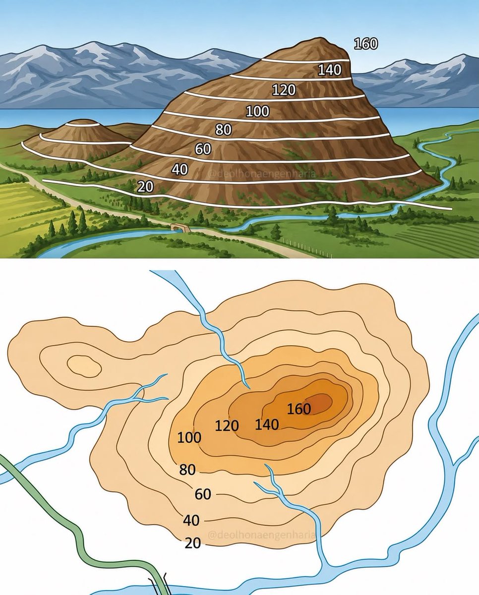
Contour lines transform the terrain into a map, enabling the precise visualisation of elevation and slope. Understanding this representation is essential for engineering, surveying, infrastructure, and land-use planning projects
Engineering Clarified tweet media
English
0
31
197
6.1K
Engineering Clarified
Engineering Clarified@EngClarified·
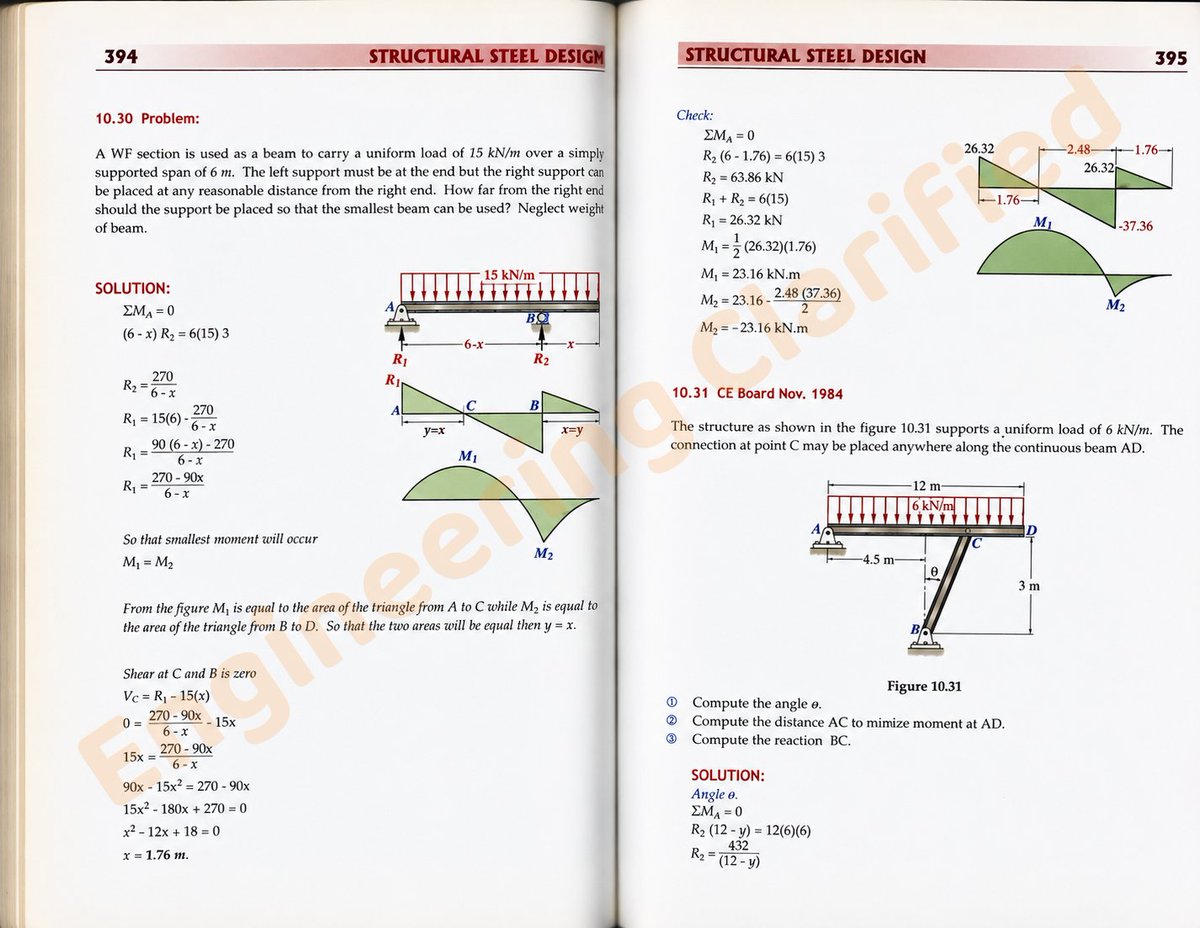
A WF section is used as a beam to carry a uniform load of 15 kN/m over a simply supported span of 6 m. The left support must be at the end but the right support can be placed at any reasonable distance from the right end..... Book name: Simplified steel design
Engineering Clarified tweet media
English
2
2
34
1.3K
Engineering Clarified
Engineering Clarified@EngClarified·
As shown in the figure, a rigid beam with negligible mass is pinned at one end and supported by two rods. The beam was initially horizontal before the load P was applied.
Engineering Clarified tweet media
English
0
3
37
1.6K
Engineering Clarified
Engineering Clarified@EngClarified·
The staircase tower combines vertical circulation with integrated seating. creating functional pause points for informal discussions and social interaction.
Engineering Clarified tweet media
English
0
4
59
1.9K