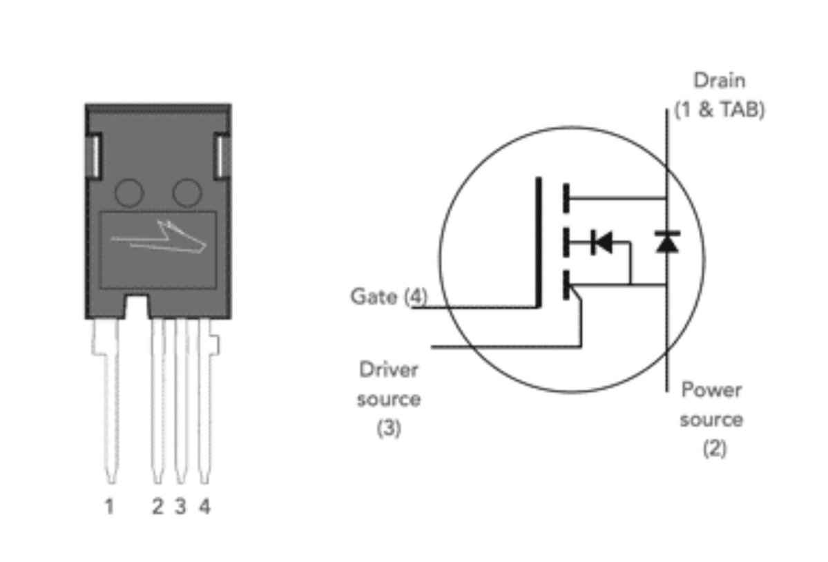
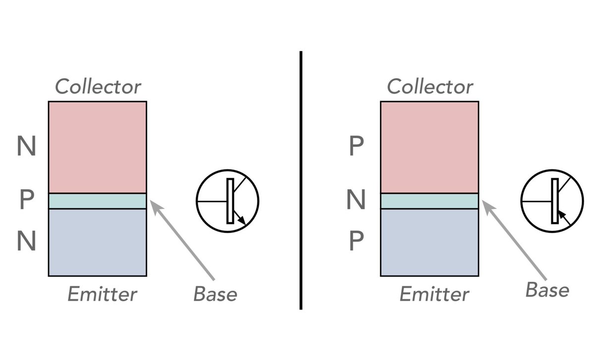
ElectronicsNotes by Ian Poole

25.7K posts

ElectronicsNotes by Ian Poole banner
ElectronicsNotes by Ian Poole

ElectronicsNotes by Ian Poole

@ElecNotes

Clear electronics/RF guides, videos & downloads by Ian Poole | Resource hub for engineers & hobbyists | Shop: https://t.co/EkY2CQby9c

South East, England Inscrit le Kasım 2016
265 Abonnements16K Abonnés
ElectronicsNotes by Ian Poole
What Actually is the Kelvin Emitter Terminal used on IGBTs and SiC Power MOSFETs Some IGBTs and SiC MOSFETs have an additional terminal known as a Kelvin emitter. It may be wondered what this is and how it should be used. All will be explained . . . . This extra terminal is connected to the emitter but routed from the die to the outside world as a separate terminal. The Kelvin emitter is essentially a dedicated connection to the emitter terminal that is separate from the main power current path. Its primary purpose is to provide a clean reference point for the gate drive circuit, minimizing the impact of voltage drops caused by the high switching currents flowing through the parasitic inductance and resistance of the main emitter connection. The presence of a Kelvin emitter terminal provides a number of benefits: Electronic components database Accurate Gate Voltage Control:   High and rapidly changing currents in the power emitter lead can induce voltage drops. If the gate drive circuit uses this point as its reference, these voltage fluctuations can interfere with the actual gate-emitter voltage seen by the IGBT die.
The Kelvin emitter terminal, carrying only the very small gate drive return current, avoids these voltage drops, ensuring a more accurate and stable VGE for precise switching control. Improved Switching Performance:   By providing a clean gate drive reference, the Kelvin emitter helps to achieve faster and cleaner switching transitions (both turn-on and turn-off). This reduces switching losses and allows for higher operating frequencies. Enhanced Noise Immunity:   The separation of the control and power paths improves the noise immunity of the gate drive circuit. Voltage transients on the power emitter are less likely to couple into the sensitive gate drive circuitry. Reduced Oscillations:   More precise gate voltage control, thanks to the Kelvin emitter, can help to dampen oscillations and ringing during switching transitions, leading to improved EMI (electromagnetic interference) performance. Facilitates Optimized Gate Drive Design:   With a more predictable and stable gate-emitter voltage, engineers can design more effective gate drive circuits, optimizing switching speed and minimizing losses without being overly affected by the power loop parasitics. In essence, the Kelvin emitter is a technique, often implemented as an extra pin on the IGBT package (typically in a 4-pin configuration), to implement a four-terminal connection to the emitter. So it’s really a very useful terminal where high current levels are being used. #IGBT #insulatedgatebipolartransistor #electroniccomponents #kelvinterminal #powerswitching #powerelectronics #electronicsnotes
ElectronicsNotes by Ian Poole tweet media
English
1
0
3
31
Mike Cowgill
Mike Cowgill@MikeCowgill·
@ElecNotes I should say my daily driver is/are a Fluke 233 and Textronix 4020 bench meter. That's how I test the accuracy of the cheapies.
English
1
0
0
5
ElectronicsNotes by Ian Poole
Cheap vs Expensive Digital Multimeters: What’s the Difference? When diving into the world of electronics, one of the first tools you might consider purchasing is a digital multimeter (DMM). But with prices ranging from a few dollars to several hundred, how do you decide what's worth your investment? Let's break down the key differences. Accuracy & Precision: - Cheap: Often less accurate, with errors that can exceed ±2 or 3% - Expensive: They can sometimes boast an accuracy down to ±0.1%, and they can be crucial for precision work. Features & Functionality: - Cheap: Basic measurements like voltage, current, and resistance. They often have some other ranges and functions but they tend to be more limited. - Expensive: Come with a plethora of features including capacitance, inductance, temperature, frequency, and more. They offer true RMS for AC measurements, data logging, and even Bluetooth connectivity for data transfer. Build Quality & Durability: - Cheap: Typically made with less durable materials, leading to shorter lifespan and susceptibility to damage. Cost of manufacture is a key consideration. - Expensive: Designed for longevity with robust casing, shock-resistant features, and often come with warranties. They're built for the rough and tumble of daily use in professional environments. Safety: - Cheap: Might not comply with safety standards like CAT ratings, posing risks in high-voltage scenarios. - Expensive: Adhere to or exceed safety standards (e.g., CAT III, CAT IV), providing protection against electrical hazards. They include features like fused inputs to prevent damage from overloads. User Interface & Ease of Use: - Cheap: Simpler interfaces with basic displays, sometimes lacking backlighting or intuitive controls. - Expensive: Feature sophisticated, easy-to-read displays, often with graphical capabilities, auto-ranging, and ergonomic designs for one-handed operation. Calibration & Maintenance: - Cheap: Often not designed for easy recalibration; once they go off, they're generally replaced rather than fixed. - Expensive: Usually come with calibration services or the ability to be recalibrated, ensuring long-term accuracy. For Whom? - Cheap: Perfect for hobbyists, beginners, or for non-critical measurements where precision isn't paramount. Great for educational purposes or basic troubleshooting. But beware if using them on higher voltages. - Expensive: Essential for professionals, those working with sensitive equipment, or in environments where accuracy and safety are non-negotiable. While a cheap multimeter can be a good starting point, the investment in a more expensive one pays off in reliability, safety, and precision. Consider your real needs before making a decision. What are your thoughts about digital multimeters? #dmm #digitalmultimeter #testinstrument #testmeter #electronicsnotes
ElectronicsNotes by Ian Poole tweet media
English
7
5
32
2.4K
Mike Cowgill
Mike Cowgill@MikeCowgill·
@ElecNotes My experience is that the cheap ones are usually very accurate on voltage and current. Resistance isn't bad. I keep a Lidl meter in the car for 12V and fuse testing, its more than fine. Its probably fine on 240VAC too, but I wouldn't trust a £6 Chinese special.
English
2
0
0
27
Little John Fella 🇺🇦🇬🇪 🫐
@ElecNotes My main complaints are that it doesn't have an audible continuity test and that it's sampling rate is very slow. Less than 10hz. I'm considering an upgrade, but not sure what to buy.
English
1
0
0
8
Jim Edmondson
Jim Edmondson@TubeAmpTinker·
@ElecNotes There are three variables to consider in building, low cost, speed and quality… but you can only have two.
English
1
0
0
24
ElectronicsNotes by Ian Poole
Isn't this so true: To spot the real expert, choose the person who predicts the job will take the longest and cost the most. Usually when creating estimates, management goes for the lower cost, shorter timescale options because of the pressure they are under, but in reality a job takes the cost and time it takes.
English
6
0
7
509
wrexrrw
wrexrrw@wrexrrw·
@ElecNotes By some fluke, I leaned early on to just buy Fluke
English
1
0
0
49
ArendPaul Spijkerman
ArendPaul Spijkerman@apspijkerman·
@ElecNotes And i guess aluminium ranks 4th in electric conductivity .. and is used in things like overhead power transmission lines and as wiring in the airbus A380 saving 500kg's of weight.
English
0
0
0
10
ElectronicsNotes by Ian Poole
Gold Isn't The Best Conductor So Why is it Used in Electronics? You see gold-plated connectors everywhere, from high-end audio gear to spacecraft. But here’s the shocker: Gold is NOT the best conductor of electricity. The Conductivity Leaderboard If we look at electrical resistivity (ρ) at 20°C, the "medals" for conductivity are actually swapped: 🥇 Gold Medal goes to Silver: The ultimate conductor (1.59×10⁻⁸ Ω⋅m). 🥈 Silver Medal goes to Copper: The industry standard (1.68×10⁻⁸ Ω⋅m). 🥉 Bronze Medal goes to Gold: Actually the least conductive of the three (2.44×10⁻⁸ Ω⋅m). So why use Gold? If gold is in third place, why is it the gold standard for connectors? Find out in my video: youtube.com/shorts/L7gv0FC… #gold #conductivity #connectors #elrctronicsconnectors #electroniccomponents #electronicsnotes
YouTube video
YouTube
ElectronicsNotes by Ian Poole tweet media
English
11
4
30
1.9K
M
M@Chicagomike666·
@ElecNotes one word: auto-ranging
English
1
0
0
65
ElectronicsNotes by Ian Poole
Great Infographic PDF Downloads I've just added my selection of infographics or cheat sheets to my new online shop. I think this presents them rather well. Covering topics from the Resistor Colour Code to Capacitance Basics, Transistor Circuit Configurations, Common Op-Amp Circuits and more, these downloads are very budget friendly, costing around $2 or equivalent. Check out my selection today: electronics-notes.com/store-shop/mer… #infographic #infographics #cheatsheets #electronics #STEM #electronicsnotes
ElectronicsNotes by Ian Poole tweet media
English
0
1
9
563
Brady
Brady@BradyRMayes·
@ElecNotes I feel like Schottky diodes should be learned first because they show the significance of non-ohmic contacts (i.e. they're nonlinear and can sometimes rectify).
English
1
0
1
13
ElectronicsNotes by Ian Poole
Are Standard PN diodes are Killing your Power Efficiency& RF Sensitivity? Here is why the Schottky Diode is the secret to high-speed switching and many other electronics circuit design performance issues. If you’re designing a power supply or a high-frequency circuit, the "standard" diode might not always be your best friend. Selecting the right electronic component is key. Choosing between a PN Junction and a Schottky Diode can be the difference between a cool-running board and a thermal meltdown. Here is the breakdown of the three "Big Dividers": 1. Forward Voltage (V_f) * Standard PN: Typically drops about 0.7V. It’s the reliable workhorse, but that voltage drop turns into heat. * Schottky: Uses a metal-semiconductor junction to achieve a much lower drop, usually 0.15V to 0.45V. * The Result: Higher efficiency and less wasted power. 2. Switching Speed & Recovery * Standard PN: These suffer from Reverse Recovery Time. When you switch them off, electrons have to "recombine," causing a brief lag. * Schottky: They are majority carrier devices. There is virtually no stored charge to dissipate, meaning they switch almost instantaneously. * The Result: Essential for high-speed switching and RF applications. 3. Reverse Leakage & Voltage * Standard PN: High "blocking" capability (can handle 1000V+) and very low leakage current. * Schottky: They are notoriously "leaky" at high temperatures and generally have lower breakdown voltages (usually capped around 100V or a little more). * The Result: If you need to block high voltage reliably, stick with Silicon or use silicon carbide Schottky diodes. Where are they used? * Standard PN Junction: general rectification, high voltage applications, general purpose circuits Schottky Diode: power supplies, solar panel circuits, RF mixers, RF signal detectors, logic ICs Pro Tip: Always check your thermal overhead. A Schottky’s low forward voltage is great, but if your environment is already hot, that increased reverse leakage can rocket upwards. Where have you used either of these diodes? #ElectricalEngineering #PCBDesign #diodes #Semiconductors #PowerElectronics #electroniccomponents #TechTips
ElectronicsNotes by Ian Poole tweet media
English
3
1
25
904
Brady
Brady@BradyRMayes·
@ElecNotes Be sure to factor in any pourosity in gold plating. The gold itself may be a noble metal, but pores that expose underlying material will make it as useful as a sceen door on a submarine.
English
1
0
1
16
ChristophPeterS
ChristophPeterS@CPeterS47·
@ElecNotes If one only cares about efficiency- and totally ignores circuit complexity- then one may replace the diodes by MOSFET switches. Their control is delicate, but it is done. It is not for beginners anyhow…
English
1
0
0
14
TAG
TAG@TBKG_25·
@ElecNotes 🤔....Gold is impervious to oxidation and chemical attack? Can ensure continuous long term contact with solders and conductive adhesives.
English
1
0
2
21
∀lan ∃liasen
∀lan ∃liasen@aeliasen·
@ElecNotes In my Electrical Engineering university classes, 99% of the analysis of transistor circuits used NPN transistors. It may just be EEs are more used to analyzing and designing with them.
English
1
0
0
5
ElectronicsNotes by Ian Poole
Why are NPN transistors more widely used than NPN? While both NPN and PNP bipolar junction transistors (BJTs) are essential tools for engineers, NPN versions are significantly more popular. If you’ve spent any time looking at datasheets or schematics, you’ll notice they dominate the landscape. Based on insights from Electronics Notes, here are the three primary reasons why NPN is the go-to choice: 1. Faster Performance (Carrier Mobility) The biggest technical advantage comes down to physics. NPN transistors use electrons as their majority charge carriers, while PNP transistors rely on holes. • Electrons move much more freely and quickly through the crystal lattice of the silicon than holes do. • This higher "mobility" means NPN transistors can switch faster and provide better performance in high-frequency applications. 2. Standardized Negative Grounding In the world of electronics—from automotive systems to consumer gadgets—negative grounding has become the universal standard. • The polarity of NPN transistors is naturally compatible with negative ground configurations. • This makes them easier to integrate into standard circuit designs without needing complex power supply arrangements. 3. Lower Production Costs Manufacturing economics play a huge role. Most silicon-based components are most efficiently produced using large N-type silicon wafers. • Interestingly, producing a PNP transistor with equivalent performance to an NPN often requires nearly three times more surface area on the wafer. • Since wafer space is at a premium, this makes PNP transistors more expensive to manufacture, driving the industry toward the more cost-effective NPN alternative. The Bottom Line: While PNP transistors are still vital for specific tasks (like push-pull amplifiers or high-side switching), the NPN transistor's speed, compatibility, and cost-efficiency make it the undisputed heavyweight champion of the bipolar world. #Electronics #electroniccomponents #ElectricalEngineering #TechTips #Transistors #NPN #PNP #electronicsnotes
ElectronicsNotes by Ian Poole tweet media
English
17
25
180
8.7K
ArendPaul Spijkerman
ArendPaul Spijkerman@apspijkerman·
@ElecNotes During WW2 the Manhattan Project borrowed 14,000 tons of silver from US treasury to make electromagnet windings to separate isotopes of uranium. So they didnt have to use copper needed for the war i guess. And eventually they gave the silver back.
English
1
0
0
49