
Arsenal1886
709 posts


Now why bowtie antenna you ask?
Go back to dipole/ halfwave dipole you often design them for one frequency, it is fixed by length but for bowtie they go with the angle.
What's actually happening: the flared shape means current has tons of different path lengths available on the same structure. At the feedpoint, the shorter paths handle higher frequencies. Out toward the wider edges, longer paths handle lower frequencies.
I think of it as basically several different "dipole lengths" stacked into one continuous shape.
That's why a bowtie gets ~33% bandwidth vs ~8% for a thin dipole it's not one antenna tuned to one freq, it's a bunch of slightly different ones overlapping. (Wideband)
antenna-theory.com/antennas/wideb…
English
The antenna is: bow tie antenna, the shape sort of gives it away.
Now coming to the circuit:
This circuit is called a comb generator, this particular model probably generates 100MHz spaced signal cuz that's the oscillator used.
These are widely used in EMI/EMC testing if I'm not wrong.
A clock's trapezoidal edges create harmonics via the sinc-function envelope now A comb generator is designed to maximize this: it drives a nonlinear element (step-recovery diode mostly) as hard as possible with a fast transition edge drive signal, generating a dense, flat "comb" of harmonics spanning octaves.
100 MHz crystal oscillator (the "100.00R EC3951" XO) generates the fundamental which drives a balun for balanced coupling and into what I'm guessing is an SRD (the banded SOD323 package sitting right at the balun op but, it could just be a Schottky, hard to confirm). The SK17 Schottky downstream looks like it's serving a separate function not sure...
Op should look like this in the SA


Mehdi@MehdiHacks
RF quiz: what does this circuit do? Will post the answer in the morning.
English
Arsenal1886 retweetledi
@MehdiHacks A guy with no experience here:
No idea about the functionality but I guess the antenna is dipole🤔
English

Arsenal1886 retweetledi


Arsenal1886 retweetledi


Arsenal1886 retweetledi


Arsenal1886 retweetledi

Imagina escribir una tesis doctoral tan fundamental que el título sea literalmente solo el nombre de todo el campo de estudio.
Paul Dirac, 1926: "Mecánica Cuántica."


Español
Arsenal1886 retweetledi

Multistage Wilkinson. Increasing the bandwidth of the divider/combiner by adding poles, probably based on a Chebyshev polynomial function, like most RF bandpass filters.
Also when properly tuned, it has the effect of minimizing group delay fluctuation across the band (minimal phase distortion)
English
Arsenal1886 retweetledi

Answer: it's a multi section Wilkinson divider.
Here's the stylized picture and also the full product picture.
As you see, it's a cascade of multiple quarter wave sections for wideband operation.
The cost is bigger size, more resistors, a bit more difficult implementation etc.
To reduce the size they use meander or serpentine geometries (basically they fold the lines back and forth to compress the length.
The product is a Mini Circuits splitter (450-7500 MHz)


Mehdi@MehdiHacks
Ok let's do another quiz. A bit more difficult. This is a also a 2-way splitter/combiner, but why is it shaped like this? What is this construction called?
English
Arsenal1886 retweetledi

Guided missile of early 1960. Note how much electronics you need when there is no Microprocessor available
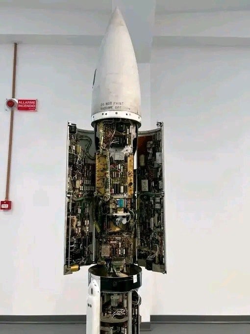

English
Arsenal1886 retweetledi


Arsenal1886 retweetledi

کسی که هواپیمای مسافربری #ps752 زده و چند روز انکار کرده، کسی که به بیمارستانها حمله میکرده و دکترها و پرستارها رو دستگیر میکرده و تیر خلاص میزده
همون هم مدارس رو میزنه که کشته سازی به نفع خودش انجام بده
دریای حرومزادگی جمهوری اسلامی پایانی نداره
فارسی
Arsenal1886 retweetledi


Arsenal1886 retweetledi

نمیشه شاه که برگشت ما هم دوباره ۱۸ سالمون شه و ایندفعه بجای اینکه سوار هواپیما شیم و توی غربت دنبال خوشبختی بگردیم،بمونیم توی کشور خودمون و همونجا خوشبخت شیم؟
نمیشه شاه که برگشت اونهمه دستهگلامون که دو ماه پیش رفتن دوباره زنده شن و کنار هم خوشبخت زندگی کنیم؟
افسوس و هزار افسوس
فارسی
Arsenal1886 retweetledi

I’m Iranian.
1.Bombs are scary.
2.Regime is scarier than bombs.
English
Arsenal1886 retweetledi

اینترنت رو قطع کرده، ماهواره رو پارازیت میاندازه و اگه جایی هم هشدار تخلیه بیاد نه آژیر میزنه، نه اطلاعرسانی میکنه. نیروهاشم میبره تو مسجد و مدرسه و اتوبوس وسط میدونهای شهر پناه میده. جنایتکار واقعی فقط و فقط خود جمهوریاسلامیه.
فارسی
Arsenal1886 retweetledi

- مدرسه زدند
+ رژیم همین سه سال پیش باعث مسمومیت شیمیایی در مدارس شد
- بیمارستان زدند
+ ماموران رژیم همین دو ماه پیش وارد بیمارستانها شدند و به مجروحین تیر خلاص زدند
-زیرساختها داره نابود میشه
+ رژیم ۴۷ ساله که داره دوه دونه تمام زیرساختهای موجود رو از بین میبره
فارسی

After watching the Iranian revolution unfold in real time over the last week it's clear to me the world is witnessing history in the making
Unfortunately, there's an uncanny lack of coverage in the mainstream West, I hope that changes
If anyone deserves support, it's Iran 🇮🇷
English