
Matjaz
450 posts

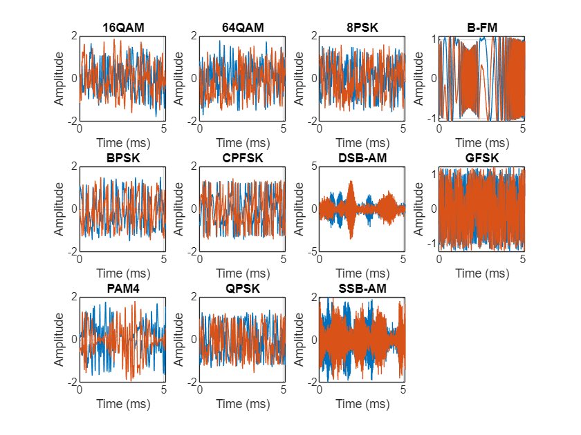
What decoder do you want implemented in CyberEther next? We have AM, FM, and ADS-B to track aircraft. What else can we add that preferentially works with an RTL-SDR?
English
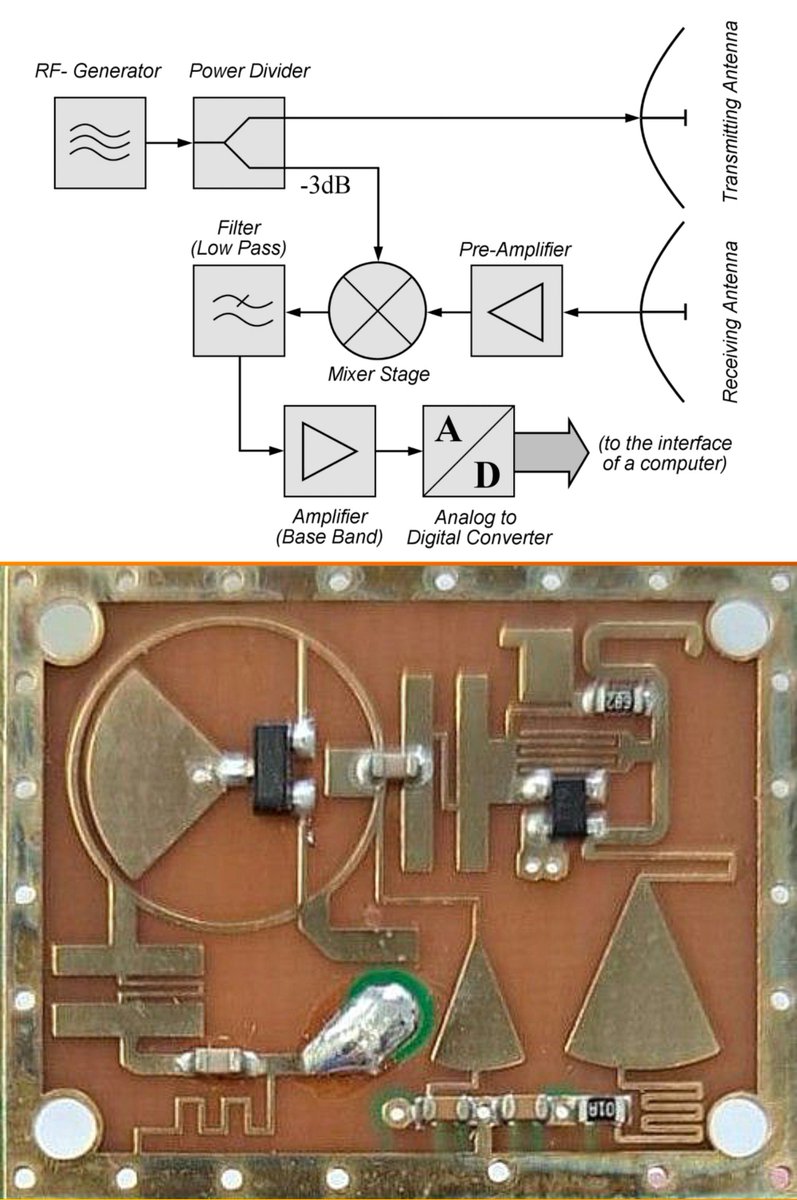
@dgo42 @MacroWorld21 This ring is a Rat-Race Mixer. Its circumference is exactly 1.5 lambda (6 * 1/4 lambda) at working frequency.
English

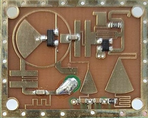
@MacroWorld21 The SOT23 in the ring - is dual diode. The ring is some art of circulator an rotate phase for bottom diode for 90° and for upper one for 270°. 4-pin device on the right side is the transistor generator using microstrip inductor and interdigital capacitor - not very stable. And ⬇️
English

Looks like the equivalent diagram simplifies it a lot 😌
So the transistor inside the ring is the oscillator, the ring is the mixer and the right chip the amplifier, the rest are filters.
English
@MacroWorld21 @dimka_rs The component inside a circle (rat-race coupler) contains 2 mixer diodes. Triangle inside represents RF ground. On the right, there’s a local oscillator with a comb filter. The left tap on circle with another filter is probably an antenna port.
English
@dimka_rs Basically the signal goes like this, not 100% accurate but follows that path..
The transistor inside the circle probably is the oscillator who can get influenced from the outside signal going in the circle, the chip in the right side might be a switch.
Easy but complicated.

English
When RF designers go circles 😄
Clever design.
English
Matjaz retweetledi

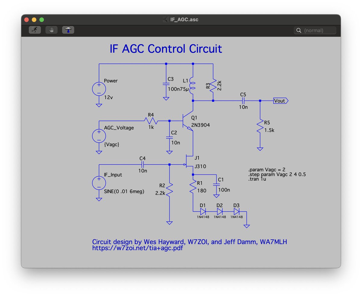
Favorite circuit of the day! Automatic Gain Control (AGC) for my homebrew SSB transceiver by Wes Hayward, W7ZOI, and Jeff Damm, WA7MLH. If you want to keep your ears from being smoked by a powerful station on your scratch built receiver, you need this circuit. #hamradio

English
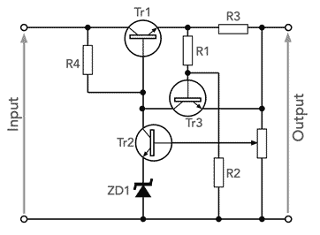
@ElecNotes You missed the point of this circuit completely! The crucial part are R1 and R2 that divide the voltage drop across the R3: less, when the load is in short-circuit and more, when it is not. In short-circuited load, the max current must be more limited, than in normal operations.
English

Foldback Current LImiter Circuits
Although constant current limiting circuits are very useful, they may not be adequate for all situations. When a fault occurs and drives the power supply into a condition where the maximum current is still delivered, it is likely that more damage may occur to the circuit being powered.
It would be very useful if the circuit would reduce the amount of current flowing when excess is required. In this way, further damage is unlikely to be caused.
The foldback circuit uses a few more electronic components, including a transistor and a few resistors, but it gives much better protection for the power supply and the circuitry being powered.
The circuit works because as the load increases, an increasing proportion of the voltage between the emitter and ground is dropped across the resistor R3 - as the load becomes smaller the potential divider effect means that more voltage is dropped across R3.
A point is reached when the transistor, TR3 starts to turn on. When this happens it starts to limit the current.
If the load resistance becomes smaller, then the voltage across R3 increases, turns on Tr3 more and this reduces the current further, folding back the level of current provided.
There are a few equations that can be used to determine the key values of the circuit to provide the required maximum current for the linear voltage regulator, and also the foldback current level on a short circuit.
In view of the fact that the regulator sense point occurs after the current sense resistor, any voltage drop across the resistor will not affect the output voltage of the circuit as this will be compensated for by the regulator. (This assumes that there is sufficient voltage across the series pass transistor for it to regulate correctly.) In this way the current sense resistor will not cause any reduction in the voltage output from the power supply regulator circuit.
The power supply current limiter circuit can be incorporated within a variety of different circuits using transistors and FETs as the series pass element. Operational amplifiers can be used as differential amplifiers to give the required voltage reference drive for the output devices.
The main issue with fold-back current limiting is that it does not always work well with non-linear loads. For example if it were to drive an incandescent lamp, where the resistance when it is cool is much lower than it is when hot, the voltage regulator with current limiter would see a very low resistance and would enter the fold-back, not allowing the lamp to heat up and start. Inductive loads can find similar issues - motors, etc have a large start-up current. This means that basic foldback current limiting is not suitable for these types of load in most cases.
Read more: electronics-notes.com/articles/analo…
English
🚨 New Project on @Hacksterio!
🐾 WildSight AI: An edge-powered system that detects wildlife & humans in real time using the AMD Kria KR260 — and alerts rangers of potential conflicts.
👉 Runs MegaDetector v5 fully on-device with Vitis AI 3.5.
hackster.io/matjaz4/wildsi…
#AI #Edge

English
@TivadarDanka Great! Now, you can continue with the e powered by i*pi. This is a very important concept in the theory of signals.
English

The way you think about the exponential function is wrong.
Don't think so? I'll convince you. Did you realize that multiplying e by itself π times doesn't make sense?
Here is what's really behind the most important function of all time:

English
@K3TripleR I have one too. Great antenna even for indoor use! I noticed that original teflon screws on the capacitor cannot be replaced by nylon screws. They become warm after few minutes and detunes the loop. Overall, I’m very satisfied with this antenna.
English


🚨 Just listed this killer 6m magnetic loop antenna on QRZ — and if you know how rare these are, you know it won’t last long.
This thing is absurdly effective for its size. I had it clamped to a balcony railing and still managed +6 dB signal reports from North Dakota on FT8. It’s like someone dared a frisbee to become a directional weapon.
✅ Ultra-portable
✅ Great for stealth ops, apartments, or portable FT8
✅ Tunable, tactical, and downright fun
You can see it in the pics — small enough to hide, strong enough to punch through the Magic Band. PSK Reporter map included for bragging rights.
If you’ve been waiting for a compact 6m solution that actually works, this is your sign.
🛑 It’s up now on QRZ.
⚡ Act fast. Before someone else snaps it up and you’re stuck with a wet noodle and regrets.
forums.qrz.com/index.php?thre…


English
🚀 Just published a full AMD Kria dev journey!
From PetaLinux setup in Docker to fully automated Ubuntu SD card image builds.
All scripts, docs & workflow on GitHub + Hackster guide 👇
🔧📦🧠
👉 hackster.io/matjaz4/kria-d…
#Kria #ZynqMP #FPGA #Linux #EdgeAI #HacksterIO
English
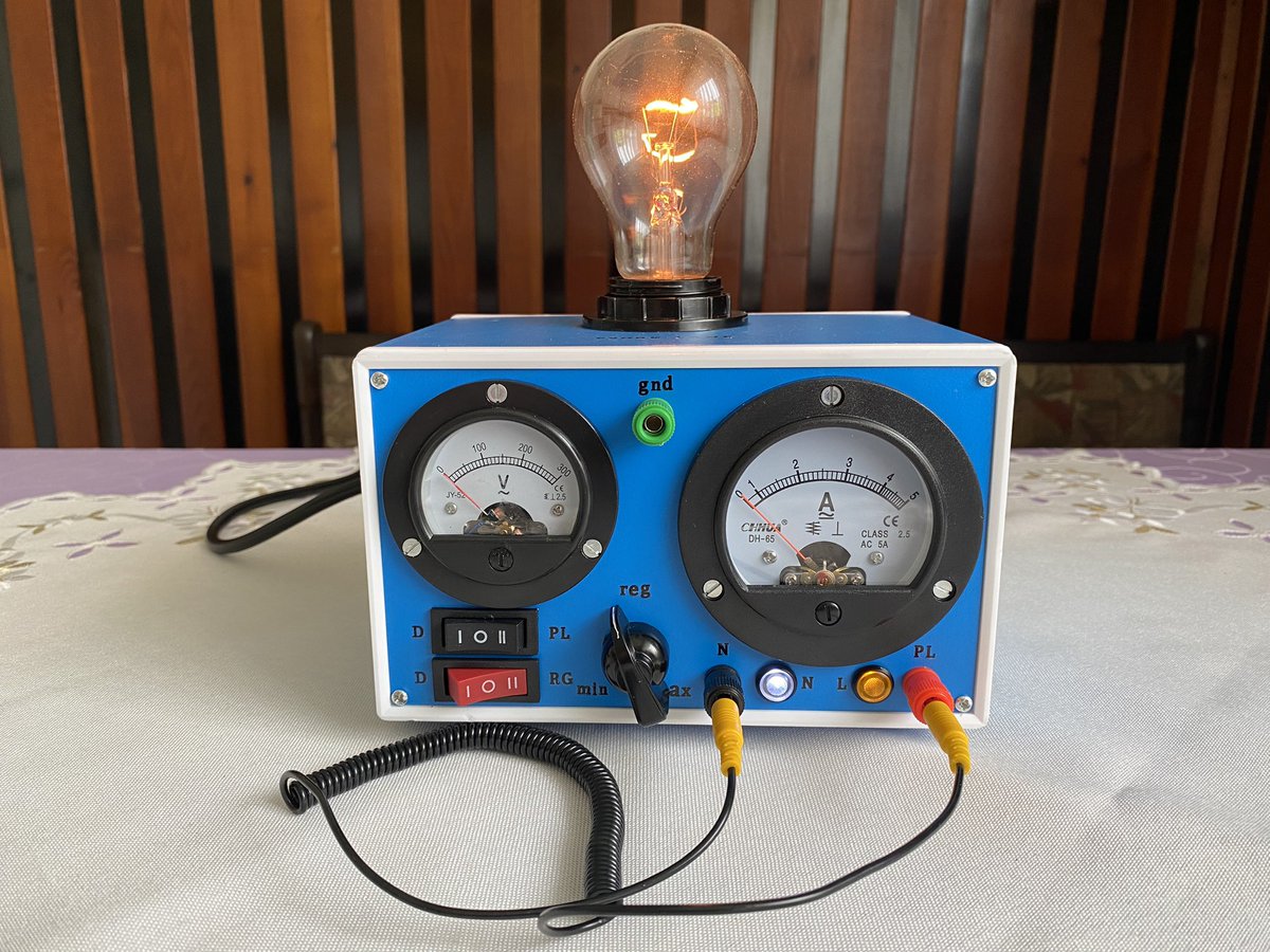
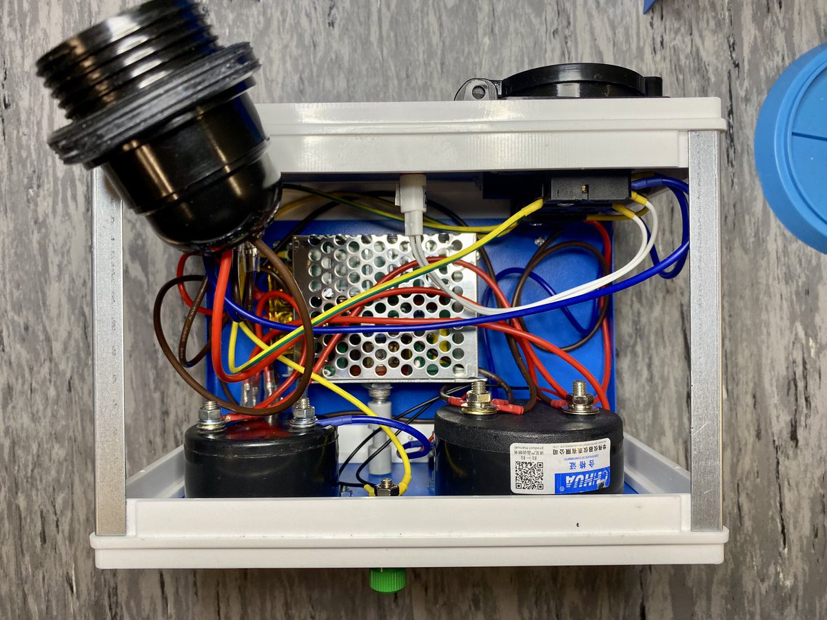
Just published my Retro Circuit & Power Tester! A vintage-style AC tester with a built-in safety bulb, analog meters, and triac regulator. Perfect for safely checking motors, appliances & DIY circuits.
hackster.io/matjaz4/retro-…
#DIY #Electronics #RetroTech #HacksterIO
English
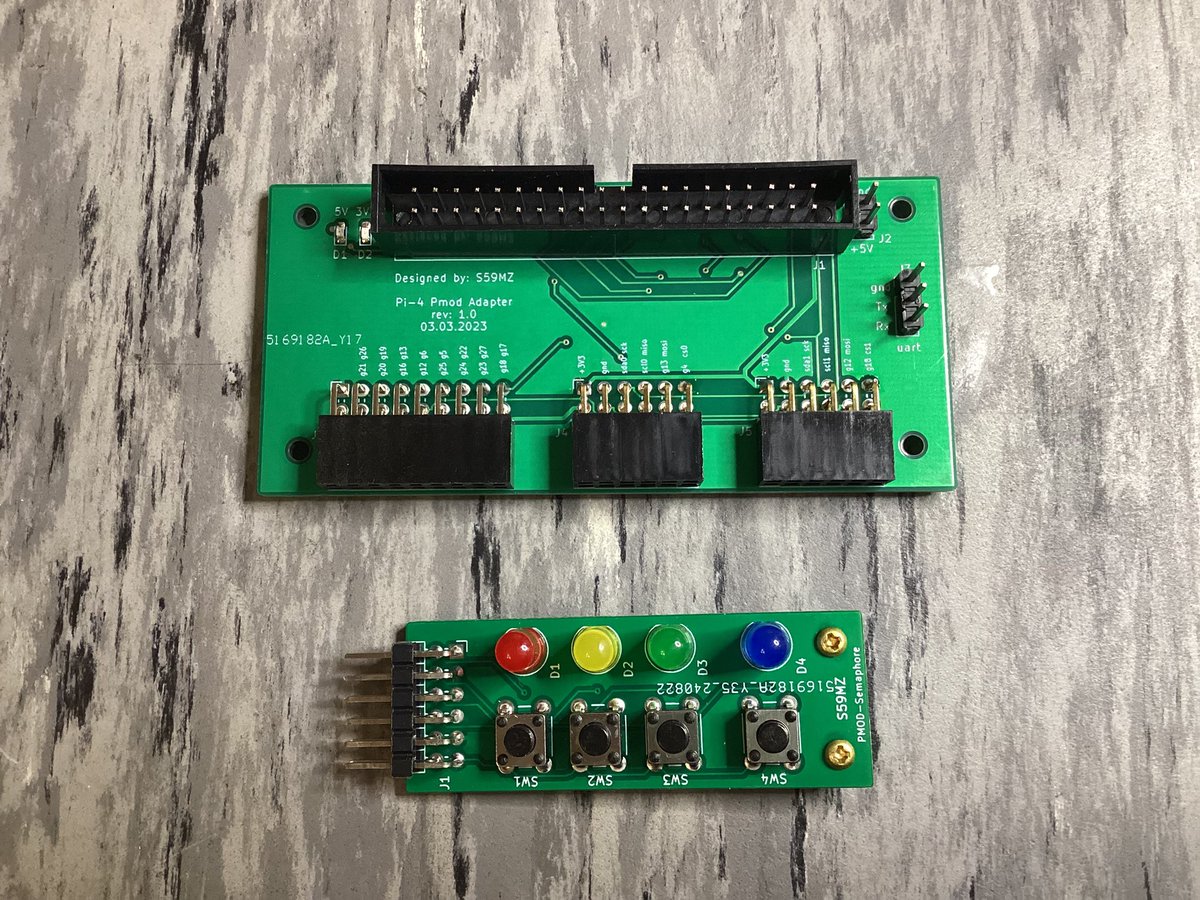
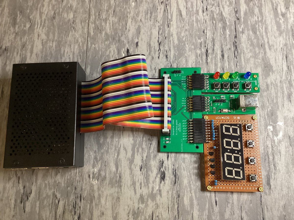
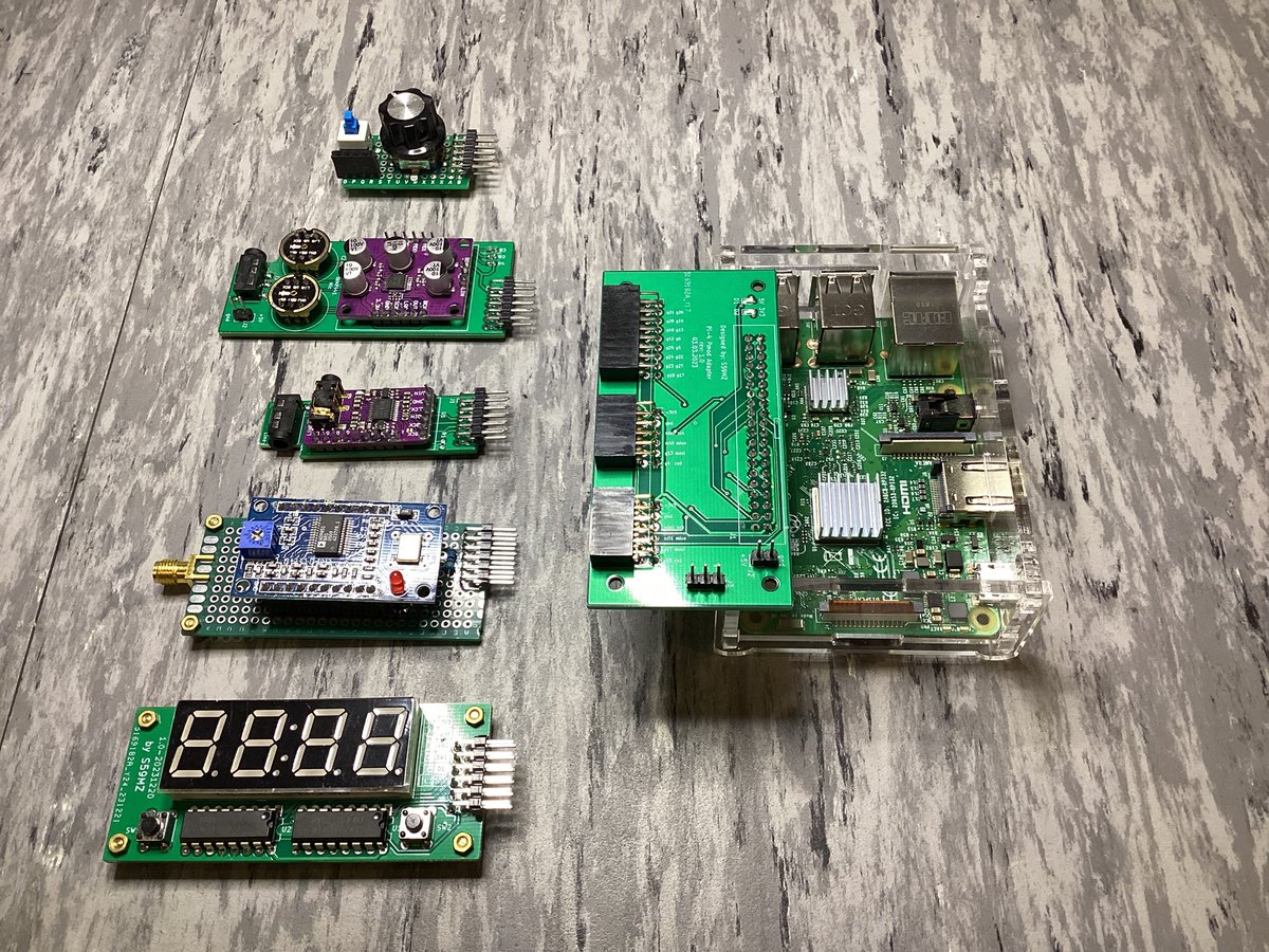
Just built a #RaspberryPi to #PMOD adapter board — super handy for kernel driver development and debugging!
Open Hardware available here:
github.com/s59mz/kicad-pi…
English
@MehdiHacks Here’s the whole step by step project and tutorial:
hackster.io/matjaz4/rf-mod…
English

@MacroWorld21 The 2 thick circles are probably rat-race mixers and the black component on circle is a pair of diodes for mixing the input signal that coming from comb filter with the LO signal. LO is implemented with dielectric resonator (DRO). It goes through Wilkinson splitter (thin circle).
English

Matjaz retweetledi

@mathladyhazel I managed to graduate from computer engineering without understanding it. I wish I had this 3Blue1Brown video back then
youtube.com/watch?v=spUNpy…

YouTube
English
Matjaz retweetledi


English


Wishing everyone a wonderful, healthy and beautiful Christmas and New Year. May the new year bring fun challenges. The first is attached. pe0sat.vgnet.nl/download/Hidde…
English
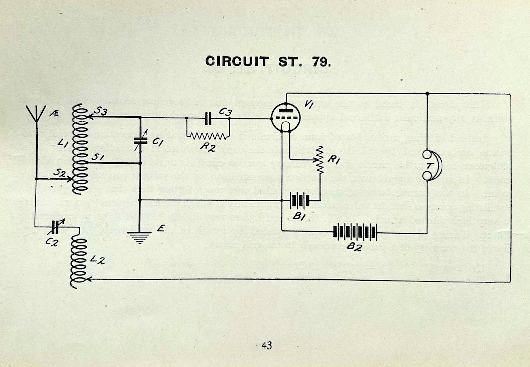
@MacDona76161341 The tube grid IS negative here, because of charged C3. It is charged on first positive half-period of RF signal and stays charged all the time. R2 is in the range of mega ohms, so the R2C3 time constant is much longer than the period of RF signal, but shorter than audio period.
English
@ElecNotes Hi,i mean: The cathode is connected to ground. On top of Ant. we have the transmitted AM positive signal received. This Signal, can only be positive. Signal is fed to the grid. A Tube grid is normally negative V. This is made by resistor Cat- Gnd. Work, but reduced lifetime
English
This is a circuit by John Scott-Taggart from 1923 for a radio receiver.
It uses the Reinartz principle and in this way it improves its performance over a straight receiver.
It uses a single valve or tube to provide the gain. The Reinartz principle invented by John Reinartz uses feedback via an inductor and capacitor.
The feedback considerably increases the gain and selectivity.
The action is obtained by means of the condenser, C2 and the coil or inductance L2.
The values shown give coverage in the approximate region of 250 - 650 metres wavelength - the units used at the time for denoting a position in the radio spectrum and on the dials of the radio receivers.
The circuit appeared in More Practical Valve Circuits by John Scott Taggart and was published around 1923.
English
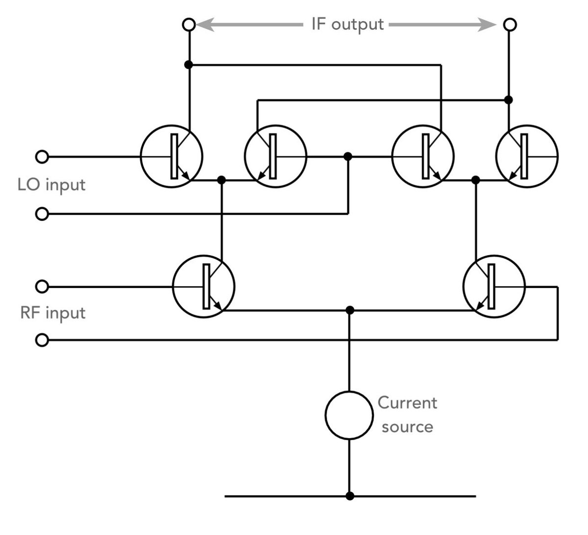
@ElecNotes To simplify: Both upper diff amps are connected together Anti-Parallel, so one amplify/multiply the input signal by positive value, while the other by negative. And the third/lower diff amp switches between those two amps, according to polarity of the local oscillator input sig.
English
Understand the Gilbert Cell RF Mixer
The Gilbert cell mixer or multiplier is a form of RF mixer circuit that is widely used in integrated circuits.
The circuit is able to provide excellent performance although it does require a larger number of components than many other forms of mixer.
The Gilbert cell mixer or Gilbert cell multiplier is a form of double balanced mixer that is able to exploit the symmetrical topology to remove the unwanted RF & LO output signals from the IF by cancellation.
As performance of adjacent components within an integrated circuit is likely to be well matched, the circuit will be well balanced and suppression of the unwanted signal components will be high.
The Gilbert cell mixer essentially comprises two differential transistor pairs whose bias current is controlled by one of the input signals. The other input signal drives the base electrodes of the differential pair transistors.
The output that results from the Gilbert cell mixer or multiplier is an accurate multiplication of the two input signals.
There are two configurations or techniques that can be used with a Gilbert cell RF mixer:
•Switching Gilbert cell mixer: When the Gilbert cell circuit is used as a switching mixer, the local oscillator input to the mixer needs to be a square wav, and there is no need for the pre-distortion circuitry. As a switching mixer, the RF port then serves as the linear input.
When used in the switching mode, the Gilbert cell mixer has a switching signal fed into the local oscillator port. This acts to multiply the signal on the RF port by either +1 or -1 - multiplying it by +1 transfers the RF input level to the output port with no change. Multiplying it by -1 inverts the output (i.e. a 180° phase change).
When used in the switching mode, the LO input of the Gilbert cell mixer does not need to exhibit high linearity (i.e. low intermodulation distortion, and harmonic distortion) as it is purely a switching signal. It does need to provide a fast switching time. It is the RF input for the Gilbert cell mixer that needs to provide the linearity.
•Analogue Gilbert cell mixer: When used as an analogue mixer, the Gilbert cell requires that one of the inputs is "pre-distorted" using a diode circuit. This is used to add a level of distortion equal and opposite to that inherent in the differential pair.
Although the diagram above shows the use of bipolar transistors, the Gilbert cell mixer can equally well use field effect transistors. The same basic concepts apply - the only real difference is in the biasing arrangements used.
English