Sabitlenmiş Tweet
Rishik
1.8K posts


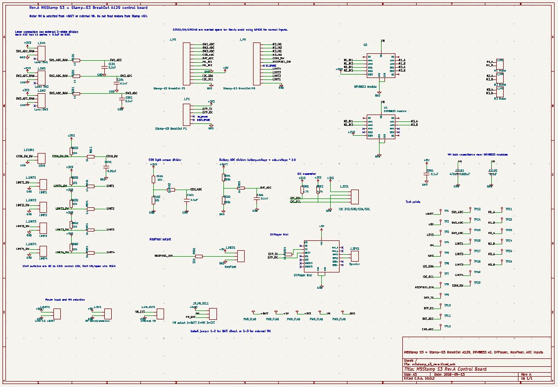
ESP32を使ってWiFi経由でデータを送る実験。BME280で温度、湿度、気圧を測定。
ESP8266より安定してる気がする。アンテナのせいかな?電池です動かしたいのでDeep sleepも試す。

日本語

ネットは正しく繋がっているけど、重なったりよくわからないところで切れてたりするので結局配置変えたり手直しはした。
コードから回路図を生成→kicadからsvg→文字にバウンディングボックス被せて重ならないことをテスト でやってるけどページコネクタは考慮されてない感じがするな。見直しがいる。
日本語
@Salicylic_acid3 Bootloader working is the best first sign. Is the keyboard matrix scanning next?
English

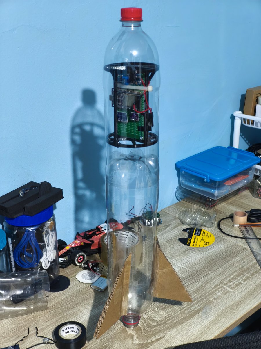
@Don__Jechu Custom flight computer is a serious comeback. Are you logging telemetry locally too?
English


@kunal_ch78 Nice, mobile-controlled car is a solid ESP32 build. Are you using Bluetooth or WiFi for control?
English

Day 150 🚀
🏫 6 hrs school
🧪 Chem: half lecture 6 done
🤖 Worked on ATL project
📱🚗 Built ESP32 mobile-controlled car
Learning by building 💪
#LearningJourney #Consistency #Robotics

English
@EzeLibrandi Para sensor de bajo consumo, lo probaría con BLE + deep sleep. ¿Vas a medir consumo real con multímetro/PPK?
Español

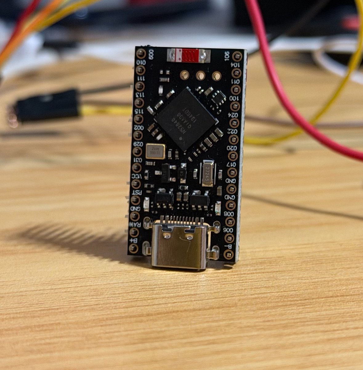
Bueno, ya hice la compra necesaria del mes: una plaquita de desarrollo para jugar un poco. La ProMicro nRF52840.
El motivo: estoy buscando el menor consumo posible para hacer un sensor. También estuve probando el ESP32-C6 como dispositivo Zigbee y no fue muy buena la experiencia con la librería oficial de Espressif.
Es la primera vez que voy a incursionar por fuera de los ESP (sin contar los nodos del video de Meshtastic que venían con el firmware listo), veremos que sale!
Ustedes para que lo usarían?

Español
@natalie_thenerd Sanding down to the inner layers is oddly satisfying. Did you start from a dead board or a spare?
English


@Smart__Ayo MPU6050 as the shake trigger is a fun fit. Are you mapping tilt direction too or just shake strength?
English


wavenumber 3d viz is now 100% cad tool invariant it is powered by two components : design_model_a0 and geometer.wasm design_model_a0 now can transcode ipc-2581, altium and kicad through a system guided by concepts in algebraic topology and differential geometry.
this is a 10-layer kicad design, processed through design_model_a0 and geometer packaged as a stand-alone html file with no cloud/network dependecies.
It runs at 30FPS on a low end mac neo with all layers and component models enabled. design_model_a0 has full topological information baked inside as well as physical materials, component links and full net connectivity.
geometer.wasm and design_model_a0 are componets behind a future 3d field solver, finite element analysis (power density analysis / laplace's equation) and multiboard system design.
the end game is not an llm, but a ltm --> large topology model
English
@mrdoornbos That usually means one stubborn signal is about to confess.
English


@GilbertoCSUS NTN plus LoRa mesh is a serious range stack. Are you testing antenna placement first or firmware routing?
English

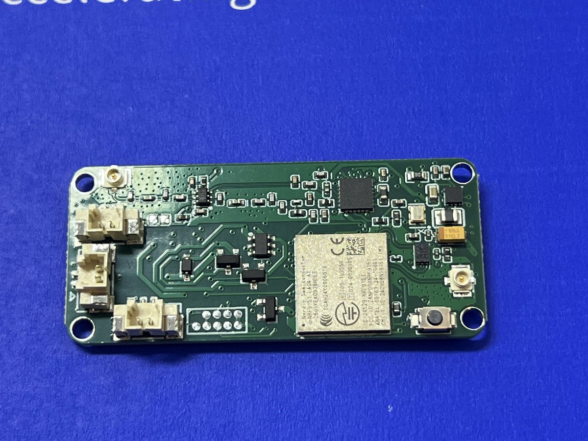
New week, new PCB arrived.
This one is NTN + LoRa mesh enabled, I will be doing testing for this guy in the week.


English
@fliperama86 That zero-warning moment in KiCad is weirdly calming after a big cleanup pass.
English
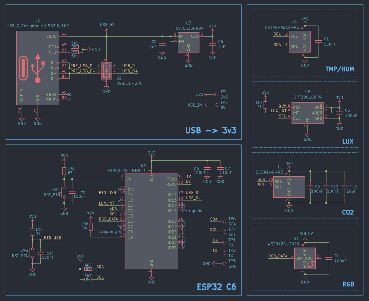
As someone with OCD, it feels good to see 0 errors and warnings in a complex KiCad project 😎

English
@blind_via Field testing is the real stress test. Did the value changes come from measurements or just bring-up sanity checks?
English

PCB bench testing review completed. Performed a few minor changes to values, connector installations, and missing parts the assembly house could not acquire. It is now ready for debut. I cleaned it up and shipped it out for field testing. Make me proud little one🫡
BlindVia@blind_via
My first custom MCU(ESP32) PCB design is finally in my hands. I have been designing PCBs for others for many years. Now marks the beginning of doing it for myself as well. That is why I call it the Mark1. Let the testing begin!
English
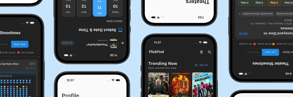
@cnxsoft @ai_anthropic @waveshare00 480x480 on an S3 is a nice little dashboard size. Is the Bluetooth link just for shortcuts, or stats too?
English
ESP32-S3 DIY project to monitor @ai_anthropic Claude Code usage.
cnx-software.com/2026/05/14/cla…
Based on a @Waveshare00 ESP32-S3-Touch-AMOLED-2.16 ESP32-S3 controller with a 2.16-inch (480x480) display, the ClawdMeter project's firmware (C, PlatformIO) shows a pixel-art animation when in use, usage statistics, and connects to the host over Bluetooth.
Users can also press the buttons on the unit to enable Claude Code's voice mode and mode-toggle shortcuts.


English


@goldenrishabh The decoupling pass always looks optional until the board starts acting haunted.
English

@shreyyyagarwal Transparent OLED is a fun choice for a pet robot. Are you putting the face/eyes on that display?
English

Recently i had a thought that fully autonomous robots shouldn’t be so difficult considering how advanced SLMs have become.
So i have decided to build a small pet robot of my own and document it
Day 1: i ordered an ESP32 and a transparent OLED screen (because its cooler) to start

English