
ElectronicsNotes by Ian Poole
25.7K posts
ElectronicsNotes by Ian Poole
@ElecNotes
Clear electronics/RF guides, videos & downloads by Ian Poole | Resource hub for engineers & hobbyists | Shop: https://t.co/EkY2CQby9c
South East, England Entrou em Kasım 2016
265 Seguindo15.9K Seguidores

@ElecNotes I feel like Schottky diodes should be learned first because they show the significance of non-ohmic contacts (i.e. they're nonlinear and can sometimes rectify).
English
Are Standard PN diodes are Killing your Power Efficiency& RF Sensitivity?
Here is why the Schottky Diode is the secret to high-speed switching and many other electronics circuit design performance issues.
If you’re designing a power supply or a high-frequency circuit, the "standard" diode might not always be your best friend.
Selecting the right electronic component is key. Choosing between a PN Junction and a Schottky Diode can be the difference between a cool-running board and a thermal meltdown.
Here is the breakdown of the three "Big Dividers":
1. Forward Voltage (V_f)
* Standard PN: Typically drops about 0.7V. It’s the reliable workhorse, but that voltage drop turns into heat.
* Schottky: Uses a metal-semiconductor junction to achieve a much lower drop, usually 0.15V to 0.45V.
* The Result: Higher efficiency and less wasted power.
2. Switching Speed & Recovery
* Standard PN: These suffer from Reverse Recovery Time. When you switch them off, electrons have to "recombine," causing a brief lag.
* Schottky: They are majority carrier devices. There is virtually no stored charge to dissipate, meaning they switch almost instantaneously.
* The Result: Essential for high-speed switching and RF applications.
3. Reverse Leakage & Voltage
* Standard PN: High "blocking" capability (can handle 1000V+) and very low leakage current.
* Schottky: They are notoriously "leaky" at high temperatures and generally have lower breakdown voltages (usually capped around 100V or a little more).
* The Result: If you need to block high voltage reliably, stick with Silicon or use silicon carbide Schottky diodes.
Where are they used?
* Standard PN Junction: general rectification, high voltage applications, general purpose circuits
Schottky Diode: power supplies, solar panel circuits, RF mixers, RF signal detectors, logic ICs
Pro Tip: Always check your thermal overhead. A Schottky’s low forward voltage is great, but if your environment is already hot, that increased reverse leakage can rocket upwards.
Where have you used either of these diodes?
#ElectricalEngineering #PCBDesign #diodes #Semiconductors #PowerElectronics #electroniccomponents #TechTips

English
@BradyRMayes That’s an important point to remember.
English
@ElecNotes Be sure to factor in any pourosity in gold plating. The gold itself may be a noble metal, but pores that expose underlying material will make it as useful as a sceen door on a submarine.
English
Gold Isn't The Best Conductor So Why is it Used in Electronics?
You see gold-plated connectors everywhere, from high-end audio gear to spacecraft. But here’s the shocker: Gold is NOT the best conductor of electricity.
The Conductivity Leaderboard If we look at electrical resistivity (ρ) at 20°C, the "medals" for conductivity are actually swapped:
🥇 Gold Medal goes to Silver: The ultimate conductor (1.59×10⁻⁸ Ω⋅m).
🥈 Silver Medal goes to Copper: The industry standard (1.68×10⁻⁸ Ω⋅m).
🥉 Bronze Medal goes to Gold: Actually the least conductive of the three (2.44×10⁻⁸ Ω⋅m).
So why use Gold?
If gold is in third place, why is it the gold standard for connectors?
Find out in my video: youtube.com/shorts/L7gv0FC…
#gold #conductivity #connectors #elrctronicsconnectors #electroniccomponents #electronicsnotes

YouTube

English

@ElecNotes If one only cares about efficiency- and totally ignores circuit complexity- then one may replace the diodes by MOSFET switches. Their control is delicate, but it is done.
It is not for beginners anyhow…
English
@TBKG_25 Definitely very much better than silver or gold from that perspective.
English

@ElecNotes 🤔....Gold is impervious to oxidation and chemical attack? Can ensure continuous long term contact with solders and conductive adhesives.
English
@aeliasen I think the better performance of NPN means that they are more widely used and hence the focus in EE courses.
English

@ElecNotes In my Electrical Engineering university classes, 99% of the analysis of transistor circuits used NPN transistors. It may just be EEs are more used to analyzing and designing with them.
English
ElectronicsNotes by Ian Poole retweetou
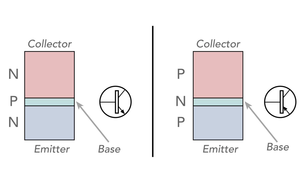
Why are NPN transistors more widely used than NPN?
While both NPN and PNP bipolar junction transistors (BJTs) are essential tools for engineers, NPN versions are significantly more popular.
If you’ve spent any time looking at datasheets or schematics, you’ll notice they dominate the landscape.
Based on insights from Electronics Notes, here are the three primary reasons why NPN is the go-to choice:
1. Faster Performance (Carrier Mobility)
The biggest technical advantage comes down to physics. NPN transistors use electrons as their majority charge carriers, while PNP transistors rely on holes.
• Electrons move much more freely and quickly through the crystal lattice of the silicon than holes do.
• This higher "mobility" means NPN transistors can switch faster and provide better performance in high-frequency applications.
2. Standardized Negative Grounding
In the world of electronics—from automotive systems to consumer gadgets—negative grounding has become the universal standard.
• The polarity of NPN transistors is naturally compatible with negative ground configurations.
• This makes them easier to integrate into standard circuit designs without needing complex power supply arrangements.
3. Lower Production Costs
Manufacturing economics play a huge role. Most silicon-based components are most efficiently produced using large N-type silicon wafers.
• Interestingly, producing a PNP transistor with equivalent performance to an NPN often requires nearly three times more surface area on the wafer.
• Since wafer space is at a premium, this makes PNP transistors more expensive to manufacture, driving the industry toward the more cost-effective NPN alternative.
The Bottom Line:
While PNP transistors are still vital for specific tasks (like push-pull amplifiers or high-side switching), the NPN transistor's speed, compatibility, and cost-efficiency make it the undisputed heavyweight champion of the bipolar world.
#Electronics #electroniccomponents #ElectricalEngineering #TechTips #Transistors #NPN #PNP #electronicsnotes
English

@apspijkerman That’s an interesting story. Thanks for posting.
English

@ElecNotes During WW2 the Manhattan Project borrowed 14,000 tons of silver from US treasury to make electromagnet windings to separate isotopes of uranium. So they didnt have to use copper needed for the war i guess. And eventually they gave the silver back.
English
Read the full deep dive here: Electronics Notes - Supercapacitors vs Batteries: electronics-notes.com/articles/elect…
English
Which is better for your design: a Supercapacitor or a Battery?
As electronics technology advances, the line between these two energy storage giants is blurring. While they both store charge, their internal "DNA" is completely different.
Based on the insights from Electronics Notes, here is a breakdown of how they stack up against each other:
Supercapacitors: The Sprinters
Supercapacitors (or ultracapacitors) store energy electrostatically. Think of them as high-speed delivery vehicles.
* High Power Density: They can dump or absorb massive amounts of energy almost instantly.
* Fast Charging: They charge in seconds, not hours.
* Infinite Stamina: They can handle hundreds of thousands of charge-discharge cycles without breaking a sweat.
* The Trade-off: They have a comparatively low energy density and they can't hold a charge for a long duration.
Batteries: The Marathon Runners
Batteries store energy chemically. They are the long-haul tankers of the electronics world.
* High Energy Density: They excel at storing large amounts of energy in a small footprint, powering devices for hours or days.
* Steady Delivery: Great for sustained power, but slower to charge and discharge.
* Limited Lifespan: Chemical reactions degrade over time, leading to a limited number of cycles (typically hundreds to a few thousand).
The Best of Both Worlds: Hybrid Solutions
Why choose one when you can use both? We are seeing a massive rise in hybrid systems. By combining them, engineers get:
* Regenerative Braking in EVs: Supercaps capture the sudden burst of energy from braking, while batteries store it for the long drive.
* Peak Power Shaving: In smartphones, supercaps handle high-drain tasks like camera flashes, protecting the battery's longevity.
Whether you are designing for the grid, an EV, or a handheld gadget, understanding these trade-offs is key to system efficiency.
#Electronics #Engineering #EnergyStorage #Supercapacitors #Batteries #EV #TechTrends #electroniccomponents #electronicsnotes
English
Discover more about Schottky diodes: electronics-notes.com/articles/elect…
English
@FnMiddle It is the lack of insulating oxidation that makes it so essential in electronic manufacture.
English

@StarryCook Absolutely - it is the lack of oxidation that means it is critical in connectors and many other areas.
English

@ElecNotes Silver conducts better but tarnishes fast. Gold stays reliable for decades. Critical in aerospace where you can't exactly schedule a repair visit!
English
@Xoey80239413 Absolutely - exactly as I explain in the video. Thanks for your comment.
English

@ElecNotes As anyone who had fancy silverware, or in my case, champagne flutes, growing up would know, sliver tarnishes easily, and gold plating is a very good solution to this. Also gold can be plated incredibly thinly.
English
@thrustermaster Yes, you don’t worry about it if it gets lost damaged or stolen. Also a cheap radio is less likely to be stolen.
English

@ElecNotes Yes i fully agree - i have it in my car and if it is stolen ok - i will survive.
English
The Baofeng UV-5R: Gateway Radio or Spectral Polluter?
The Baofeng UV-5R is arguably the most polarizing piece of gear in the amateur radio world. To some, it’s the "People’s Radio" that made the hobby accessible to a new generation.
To others, it represents the challenges of cheap manufacturing and spurious emissions.
I recently dug out my old UV-5R and looked again at using it.
After revisiting this classic handheld, here are a few of my takeaways:
✅ The Pros:
• Surprising Durability: Despite the budget price, it feels sturdy and dense in the hand—far from a "toy."
• Accessibility: At roughly $25, it’s the ultimate "beater" radio for hiking, emergency kits, or a glove box.
• Community Support: With millions sold, there is a fix, a YouTube tutorial, or a cheap accessory (like the TIDRadio Bluetooth programmer) for every possible need.
❌ The Cons:
• City "Deafness": The front-end struggles in high-RF urban environments. It simply can’t filter out noise as well as a high-end Icom or Yaesu.
• Programming Pain: Manual programming is a "form of medieval torture." Using CHIRP software or a wireless programmer is almost mandatory for a sane experience.
• Spectral Purity: It can sometimes transmit "trash" signals on harmonics—a "buy at your own risk" for technical purists.
The Verdict:
The UV-5R is the "budget hatchback" of ham radio. It isn't prestigious, and the purists might look down on it—but it’s reliable enough, infinitely modifiable, and has put more people on the air than almost any other device.
Do you keep a Baofeng in your "Go-Bag," or do you prefer to stick to the big-name brands? Let’s discuss in the comments! 👇
#HamRadio #AmateurRadio #Baofeng #UV5R #TechReview #Electronics #WirelessCommunications #electronicsnotes

English
@ElecNotes I've used mechanical latching relays for battery low voltage cut-off. Provides an air gap and reset required.
English
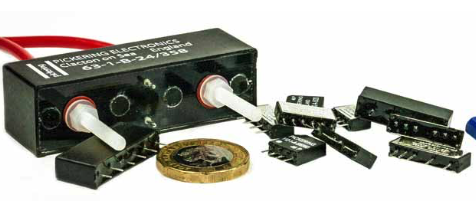
Are Reed Relays still Applicable Today, or Should They be Confined to the Outdated Bin?
In an era of Solid State Relays (SSRs) and semiconductor switching, you might think the humble reed relay is a relic of the past. But as any experienced engineer will tell you, the unique physics of the reed relay often make it the only right choice for high-precision and high-isolation applications.
Drawing from the web page on Electronics Notes, here is why reed relays remain a powerhouse in modern circuit design:
1. Galvanic Isolation is King
Unlike semiconductors, which can have leakage currents even in the "off" state, reed relays provide a true physical break in the circuit. The hermetically sealed glass envelope ensures that the switching and switched circuits are completely isolated—critical for sensitive medical or high-voltage test equipment.
2. Ultra-Low Contact Resistance
Semiconductors always have an "on-resistance" (Ron) that can drop voltage or generate heat. Reed relays use precious metal contacts (like Rhodium or Ruthenium) to provide extremely low and stable contact resistance. This makes them the gold standard for Test & Measurement matrices where signal integrity is non-negotiable.
3. Speed & Size
While not as fast as a transistor, reed relays are significantly faster than traditional electromechanical relays—often switching in less than 0.5 milliseconds. Their compact footprint (often available in SIL or DIL packages) allows for high-density switching in a very small PCB area.
4. Hermetic Reliability
Because the contacts are sealed in an inert gas (usually Nitrogen) inside a glass tube, they are immune to oxidation, moisture, and dust. This "hermetic seal" allows them to perform reliably for millions of cycles in harsh environments where open-contact relays would fail.
5. No Heat Dissipation
SSRs often require bulky heatsinks when switching current because of their internal voltage drop. Reed relays switch via mechanical contact, meaning they stay cool even when carrying their rated current, simplifying your thermal management.
Looking to master the specifics of these components? Check out my full technical guide on Electronics Notes for a breakdown of construction, magnetic screening, and internal operation:
#Electronics #Engineering #HardwareDesign #ReedRelays #EmbeddedSystems #CircuitDesign #TestAndMeasurement #ElectronicsNotes #ElectronicComponents
English
@rdavies6 @SteveTrewick How true. I totally agree with you. Unfortunately, some people can look upon them as status symbols. Personally, if I’ve got something that does what I want, that’s good for me.
English

@SteveTrewick @ElecNotes Radios should not be treated as expensive status symbols - they are tools…and sometimes the cheapest tool is ideal👍 If it gets someone on the air, and they can’t afford anything else, then it’s appropriate technology that’s doing a great job
English
Read more about electrolytic capacitors and how to use them: electronics-notes.com/articles/elect…
English
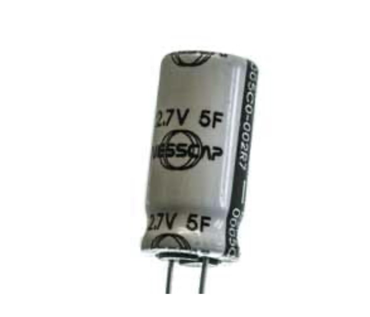
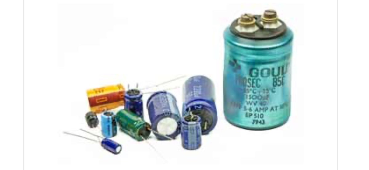
Top tips for using aluminium electrolytic capacitors
Electrolytic capacitor can have a bad name for reliability, but if used well, they can provide very reliable service. If some top tips are followed, then they can be a very good choice for a capacitor.
Aluminium electrolytic capacitors do degrade with time. Many electrolytics have a vent for allowing excess gasses to escape.
This escape can result in the electrolyte drying out and the performance of the capacitor falling.
Also if aluminium electrolytic capacitors are left for a few years, then the oxide layer on the anode can dissipate.
When this happens the capacitor needs to be repolarised. This can be done by applying a current limited voltage to the capacitor. Initially the leakage current across the capacitor will be relatively high and then it will fall as the oxide layer forms.
It is also wise to take precautions to prolong the life of the capacitor, and ensure the best overall reliability.
Below are our golden tips to maximise the life of an aluminium electrolytic capacitor and ensure the best reliability:
•Understand the essentials of electrolytic capacitors, discover their benefits & understand how they can be used to provide high levels of capacitance with high reliability with our top tips.
•Run within its voltage limits: It is always wise to run any component with a good margin below the maximum ratings. Many companies state in their design rules that for electrolytic capacitors, they should only be run at about 50% of their maximum ratings to ensure optimum reliability. If the maximum limits are exceeded then leakage current levels will rise and there is the possibility of localised breakdown leading to an explosive failure of the component.
•Keep within its current rating: In many applications an electrolytic capacitor will be required to provide high levels of ripple current. This is to be expected in applications like being used as a smoothing capacitor in a power supply. Ii is imperative to ensure that the capacitor can withstand the current being required from it. Check that the capacitor is operating within its current limits and is not becoming too warm in operation.
•Never reverse bias the capacitor: When run under a reverse bias, the leakage levels will be very much higher than in the forward direction. Again this can lead to catastrophic breakdown and failure.
•Keep temperatures down: Heat shortens the life of any aluminium electrolytic capacitor. A good rule of thumb is that every 10°C over 85°C will halve the life expectancy of the component.
•Only for lower frequencies: Electrolytic capacitors are not good when used at higher frequencies. Typically they are limited to frequencies up to a maximum of around 100kHz.
These tips will help ensure that the best performance is obtained when an electrolytic capacitor is used in an electronic circuit design, and also that they are chosen when they are the best option for the given situation.
#capacitors #electrolyticcapacitors #circuitdesign #HardwareDesign #electronicsnotes #electroniccomponents
English