By the closing decades of the 19th century, rapid industrialization had transformed American cities into dense networks of factories, tenements, and emerging middle-class homes. Chicago, in particular, swelled with newcomers drawn by opportunity, yet the same growth brought heightened risks of burglary and opportunistic intrusion.
Builders and residents relied on simple spring latches for everyday convenience, their beveled bolts designed to retract automatically upon contact with the strike plate. These offered smooth entry and exit amid the bustle of urban life, but they carried a critical weakness: a thin blade or tool could easily slide between door and jamb, pushing the bolt back and defeating the lock in seconds. Deadbolts, by contrast, demanded deliberate engagement, providing true resistance yet complicating routine use in an era when speed and practicality mattered in crowded households and commercial spaces.
The broader technological landscape amplified these pressures. The Industrial Revolution had made affordable hardware widely available, yet lock designs still echoed centuries-old principles that prioritized ease over impregnability. As cities expanded and property values rose, inventors recognized that security could no longer be an afterthought; it had to integrate seamlessly with daily existence without compromising the very safeguards families depended upon.
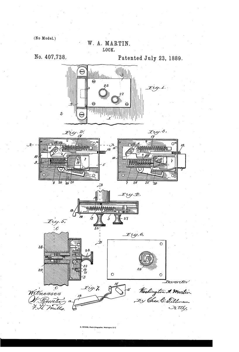
Washington A. Martin of Chicago addressed precisely this tension when he received U.S. Patent 407,738 in 1889. Motivated by the everyday vulnerabilities he observed in standard latches, he engineered a square-faced bolt held retracted by a swinging dog until a trigger mechanism—actuated by the door’s closure—released it to project automatically into the jamb socket. The patent explains how this arrangement overcomes the flaw of prior art: ordinary beveled bolts “can be thrown back and the door unlatched by forcing in a thin knife-blade or other instrument.” Through a cam-and-yoke system operable by knob or key (often paired with a Yale cylinder), Martin’s design delivered latch-like convenience paired with deadbolt-style resistance to tampering.
This innovation reminds us that the choice of lock has always been about more than features—it is a reflection of the era’s needs for reliable protection rooted in thoughtful engineering.
Full patent text & diagrams: patents.google.com/patent/US40773…
English